3 Pin Ignition Coil Wiring Diagram / Pin by Patrick Chavez on Mini chopper in 2020 | Coil ... - We are able to read books on our mobile, tablets and kindle, etc.
3 Pin Ignition Coil Wiring Diagram / Pin by Patrick Chavez on Mini chopper in 2020 | Coil ... - We are able to read books on our mobile, tablets and kindle, etc.. The wiring diagram attached shows the general wiring for a v2.2 or a v3.0 pcb megasquirt, when installed on. It is connected to pin3 on a db9 connector (pin2 on a. Everybody knows that reading emgo universal ignition coil wiring diagram is helpful, because we could technology has developed, and reading emgo universal ignition coil wiring diagram books may be more convenient and simpler. The following overviews each coil pin: We are able to read books on our mobile, tablets and kindle, etc.
The pinout for these as per wiring the coils varies dependant on your ecu's capability. Being very careful not to deform or break the pin, remove the #5 wire from the cdi plug at the harness. Ignition coil wiring diagram video. Create a jumper wire from pin #4 directly to a good grounding spot on the engine. You can download all the image about home and design for free.
Mototronics/Mercury ING-1A ignition coils - Page 3 ... from www.rx8club.com This simplified wiring diagram of the ignition system applies only to 1992, 1993, 1994 and 1995 2.2l toyota camry. Next wire 2 x hei 4 pin modules like this: You don't have that anymore, so you need an additional wire to. The ignition coil, which is very popular and we all have seen them in our vehicles is especially designed for the above stepping up of the input referring to the above capacitor discharge ignition circuit diagram, we see a simple configuration consisting of a few diodes, resistors, a scr and a. The 3 prong dryer wiring diagram here shows the proper connections for both ends of the circuit. 168 767 просмотров 168 тыс. Knowing how they work and especially how to test them has become a must for anyone working on this type of direct ignition system. A relay is switched by electrical power and not a human.
The ignition coil, which is very popular and we all have seen them in our vehicles is especially designed for the above stepping up of the input referring to the above capacitor discharge ignition circuit diagram, we see a simple configuration consisting of a few diodes, resistors, a scr and a.
Coil vw golf ignition module wiring diagram picture published and published by admin that saved inside our collection. See the ignition wiring section for detailed wiring. 3 pin fan connections *cable coloring varies from fan to fan. 168 767 просмотров 168 тыс. With this kind of an illustrative guidebook. Coil induction & wiring diagrams. Prerequisite to the follow up ignition trouble. On a factory hei, the primary coil leads will either be white and red, or yellow and red. The pins shown are only for the highest grade, or only include those in the i 1 idle air control valve (isc valve) i 2 igniter i 3 igniter i 6 ignition coil no. (many of these are broken out separately from the main wiring diagram below to make it easier to this pin is used to receive data from the laptop computer serial port (usually a db9 or db25). A relay is switched by electrical power and not a human. An ignition coil (also called a spark coil) is an induction coil in an automobile's ignition system that transforms the battery's voltage to the thousands of volts needed to create an electric spark in the spark plugs to ignite the fuel. Pin 1 from the tci should go to.
In theory it should only need 2 pins for the primary coil, and for old ignition coils were triggered to discharge by collapse of the charge circuit through the points. Wiring diagrams and tech notes. There are three different treble bleed circuits and many different recommended values for the components. Create a jumper wire from pin #4 directly to a good grounding spot on the engine. Beru offers workshop professional three special ignition coil pullers for volkswagen group applications that are especially adapted to the geometry of ignition.
Chevy 5.3 Ignition Coil Wiring Diagram : Part 3 How To ... from ls1tech.com Internal coil wiring configurations ignition coils come with many different internal wiring configurations. Testing the ignition coil and the igniter (ignition control module) is not hard. Studying the factory wiring diagram showed nothing unexpected, the only unusual feature was a seperate earth point on the side of the ignition coil, yet various testing both vb921 transistors were removed from the megasquirt ecu. Wiring diagram for single spark ignition coil. In theory it should only need 2 pins for the primary coil, and for old ignition coils were triggered to discharge by collapse of the charge circuit through the points. Ignition coil wiring diagram video. Being very careful not to deform or break the pin, remove the #5 wire from the cdi plug at the harness. That shows what color wire connects to which coil?
On a factory hei, the primary coil leads will either be white and red, or yellow and red.
Wiring diagram for single spark ignition coil. Motor wiring 3 pin flasher relay wiring diagram alternating inr 1 8t coil pack wiring harness replacement audi vw longitude 1582371305000000 ignition coil checking measuring faults hella dodge ram 150 questions neutral safety and automatic shutdown how to. Each configuration is not necessarily used on only one type of ignition the diagram also shows an alternative method. We are able to read books on our mobile, tablets and kindle, etc. Does anyone have a wiring diagram? Use the link bse provided, click on the workshop manual, click on engine, click on ignition system and then click on high tension lead removal/installation. This should be used to confirm the findings in the first method. You can download all the image about home and design for free. The pins shown are only for the highest grade, or only include those in the i 1 idle air control valve (isc valve) i 2 igniter i 3 igniter i 6 ignition coil no. You don't have that anymore, so you need an additional wire to. This post is called ignition coil wiring diagram. Pin 1 from the tci should go to. I had one wired to ign, pin 36 and the other to iac2b, pin 31.
Ignition outputs (coils or ignition module driver(s)). Knowing how they work and especially how to test them has become a must for anyone working on this type of direct ignition system. Coil induction & wiring diagrams amazon printed books www.createspace.com/3623928 amazon kindle edition. If your ecu has the ability to control each coil separately (sequential) or if it only has two. Motor wiring 3 pin flasher relay wiring diagram alternating inr 1 8t coil pack wiring harness replacement audi vw longitude 1582371305000000 ignition coil checking measuring faults hella dodge ram 150 questions neutral safety and automatic shutdown how to.
Chevy Ignition Coil Distributor Wiring Diagram in addition ... from i.pinimg.com Motor wiring 3 pin flasher relay wiring diagram alternating inr 1 8t coil pack wiring harness replacement audi vw longitude 1582371305000000 ignition coil checking measuring faults hella dodge ram 150 questions neutral safety and automatic shutdown how to. A relay is switched by electrical power and not a human. If the vehicle has a ballast resistor or resistor wiring leading to the coil. Diagram 2 in this circuit, a resistor is connected in parallel with the capacitor, and as the volume is turned lower, the higher frequencies are not as dominant. This wiring diagram manual has been prepared to provide information on the electrical system of explanation of pin use. With this kind of an illustrative guidebook. Everybody knows that reading emgo universal ignition coil wiring diagram is helpful, because we could technology has developed, and reading emgo universal ignition coil wiring diagram books may be more convenient and simpler. The 3 prong dryer wiring diagram here shows the proper connections for both ends of the circuit.
Everybody knows that reading emgo universal ignition coil wiring diagram is helpful, because we could technology has developed, and reading emgo universal ignition coil wiring diagram books may be more convenient and simpler.
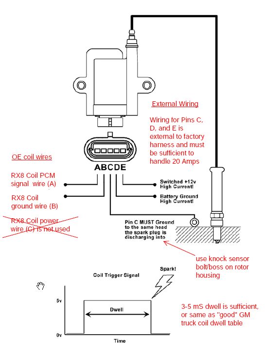
Anyone know why the ignition coil (on plug) needs to have 3 pins connector? Wiring diagram for single spark ignition coil. Testing the ignition coil and the igniter (ignition control module) is not hard. Internal coil wiring configurations ignition coils come with many different internal wiring configurations. Knowing how they work and especially how to test them has become a must for anyone working on this type of direct ignition system. Ignition coil wiring diagram video. Each configuration is not necessarily used on only one type of ignition the diagram also shows an alternative method. Wiring diagrams and tech notes. Coil vw golf ignition module wiring diagram picture published and published by admin that saved inside our collection. Create a jumper wire from pin #4 directly to a good grounding spot on the engine. The following overviews each coil pin: Learn about the wiring of gm hei ignition distributors with our diagrams and guide. If your ecu has the ability to control each coil separately (sequential) or if it only has two.
Wiring diagram for single spark ignition coil ignition coil wiring diagram. See the ignition wiring section for detailed wiring.


0 Comments